DIY Forged Carbon Recoil Cylinder for Airsoft AR15-M4: Complete Manufacturing Guide
001
002
Building a forged carbon buffer tube (recoil cylinder) is one of those projects that combines three things at once: lightness, aesthetics, and technical challenge. It’s not a trivial part, because beyond looking good it must align correctly, load, and keep the system stable.
The original Sychev Lab base already provides dimensions, materials, and assembly logic. This version reorganizes it into a clearer workshop-style guide to better understand what each part does, which tolerances matter, and where common mistakes occur.
001
What this assembly actually is
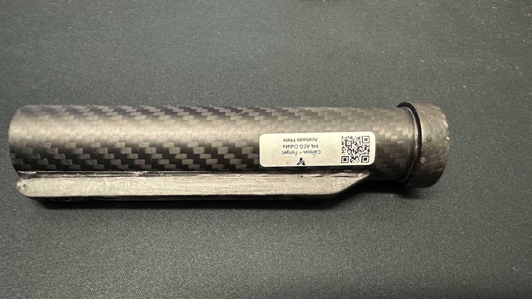
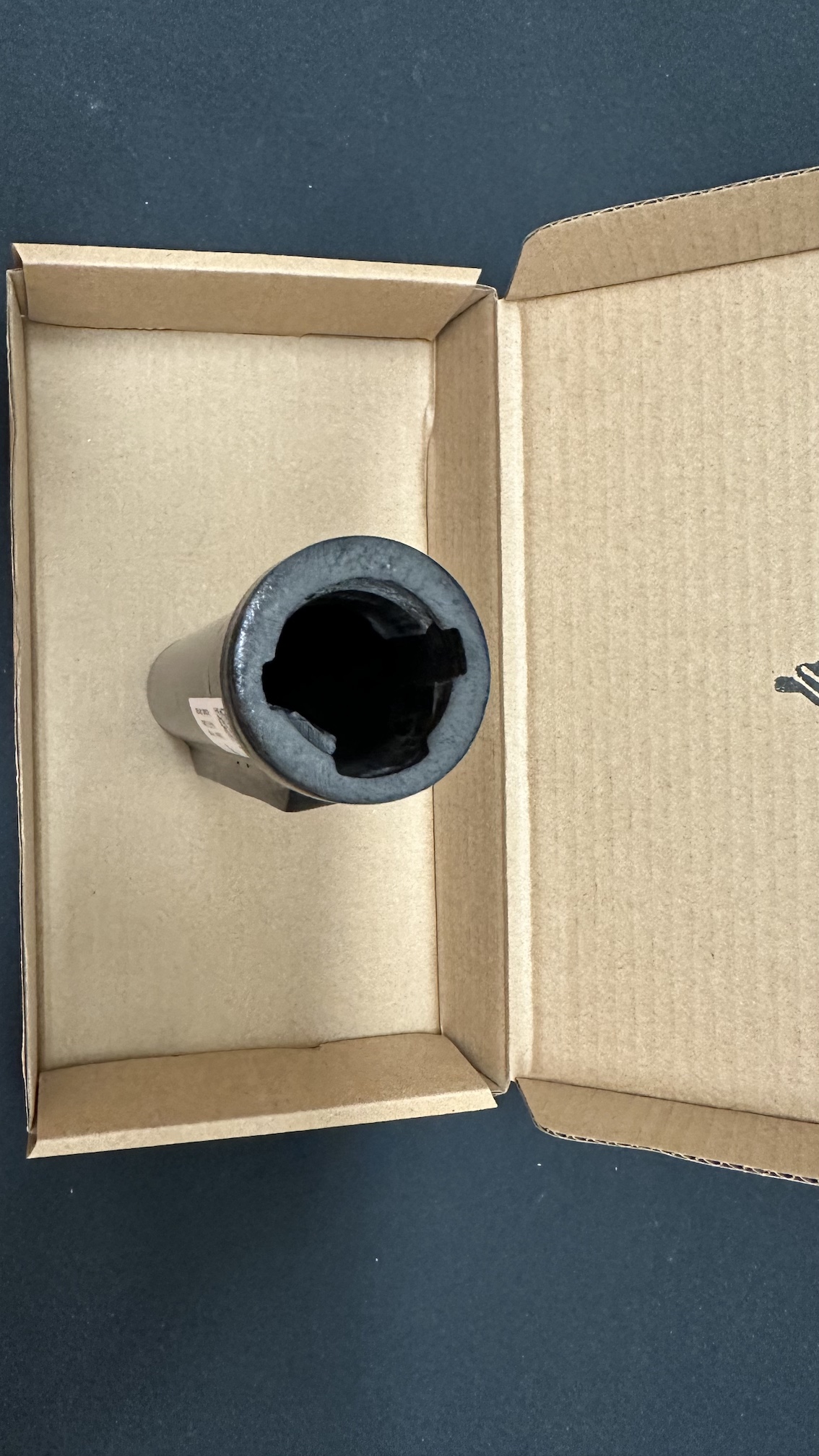
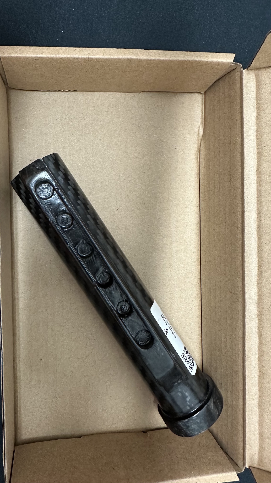
The recoil buffer tube is the rear cylinder of an AR15/M4 platform. It can house simulated recoil systems, electronics, batteries, or other components depending on the setup. In any case, it also functions as a stock support and a structural component.
In this approach, a traditional metal tube is replaced by a hybrid solution using:
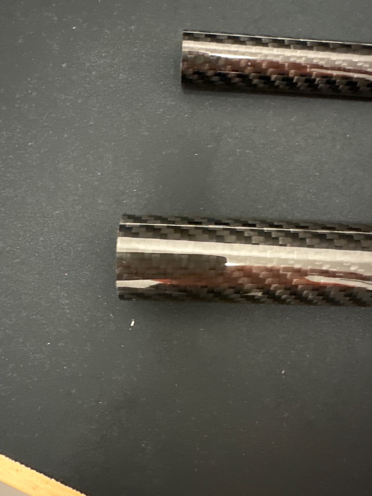
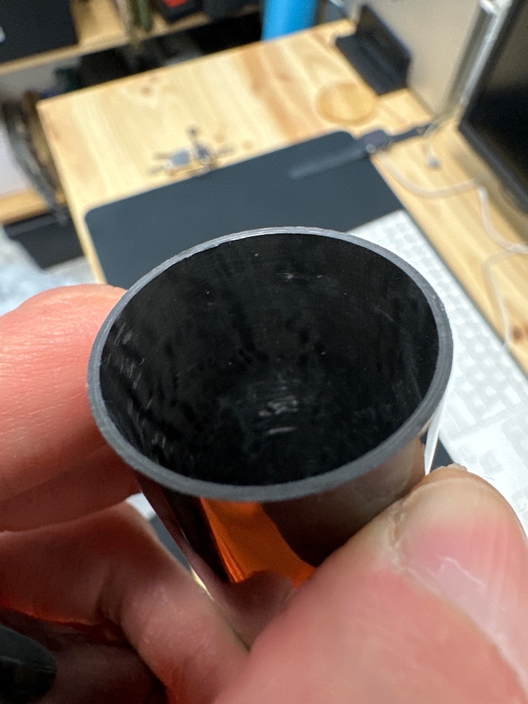
- outer carbon tube
- internal forged carbon parts
- precision bonding and assembly
Why use forged carbon here
Forged carbon combines short fibers with epoxy resin to create very lightweight yet strong parts, with a distinctive aesthetic. In this application, the main goals are:
- reduce weight
- maintain rigidity
- explore an unconventional solution
- create a custom, maker-oriented component
Materials and tools
Main materials
- carbon tube 28 × 26 × 500 mm (2 units as reference)
- chopped carbon fiber 300–500 g
- epoxy resin for composites (typical ratio 100:40)
- release agents, wax, or PTFE spray
- sandpaper (various grits)
- anaerobic adhesive (e.g. Loctite 680) for final assembly
Tools
- FDM 3D printer for molds
- manual press or bench vise
- optional oven or heated chamber for curing
- precision scale
- mixing containers, spatulas, cleaning tools
- PPE: gloves, goggles, mask
Estimated cost
The original reference places the project between €70 and €190, depending on molds, finish, and available materials. :contentReference[oaicite:0]{index=0}
The three internal components
The system relies on three main forged carbon parts:
Front bushing
Acts as the front anchor point and guide. One of the most critical elements.
Center bushing
Stabilizes and centers the system, reducing vibration and helping maintain alignment.
Rear ring
Closes the system, provides finishing, and secures the rear section.
Critical tolerances
Front bushing
- outer Ø: 25.80 ± 0.05 mm
- inner Ø: 20.00 ± 0.10 mm
- height: 35.00 ± 0.5 mm
Center bushing
- outer Ø: 25.90 ± 0.05 mm
- height: 40.00 ± 0.5 mm
- grooves: width 3 mm, depth 2 mm
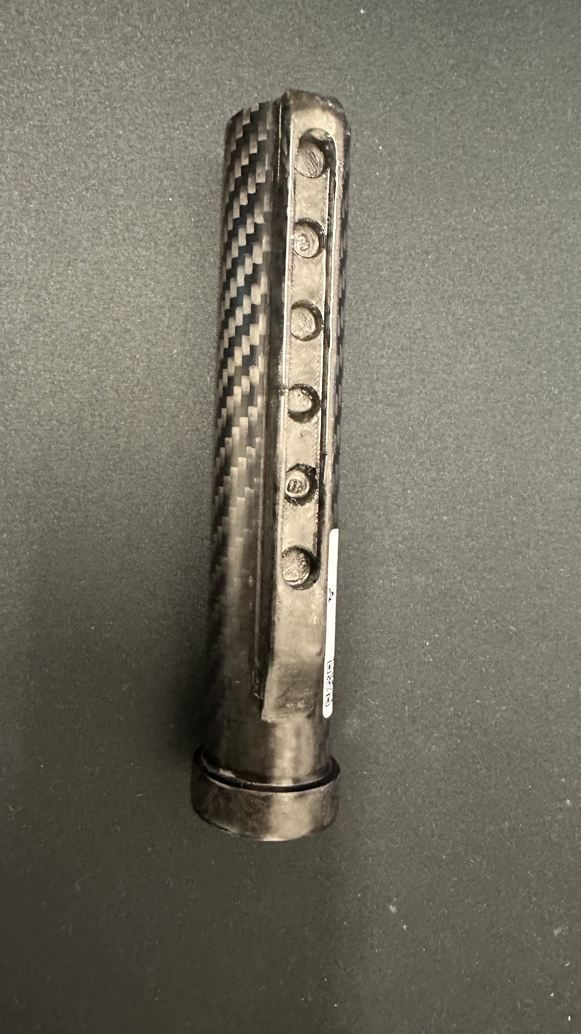
Rear ring
- inner Ø: 25.80 ± 0.05 mm
- outer Ø: 27.80 ± 0.10 mm
- height: 30.00 ± 0.5 mm
Mold preparation
Printing molds
Molds can be printed in PLA, PLA+, or PETG. Slight draft angles are important for easier demolding.
Post-processing
- light sanding
- cleaning with isopropyl alcohol
- inspection of joints and cavities
Poor mold preparation will affect demolding and final finish.
Fiber and resin preparation
For a 50 g part, the recommended ratio is approximately 60% fiber / 40% resin.
Example mix
- fiber: 30 g
- resin: 20 g
For a 100:40 epoxy:
- resin: 14.3 g
- hardener: 5.7 g
Consistency between batches is key for predictable results.
Compression molding: step by step
1. Mold preparation
- clean with isopropanol or acetone
- dry completely
- apply 2–3 layers of release agent
- let it sit as required
2. Initial loading
- add ~50% of the fiber
- compact with a spatula
- add part of the resin
3. Saturation and closing
- mix thoroughly for 2–3 minutes
- complete material loading
- close the mold
- apply slow, even pressure
4. Curing
Typical guidance:
- maintain pressure for 30–45 minutes
- optional curing at 80–120°C for 15–20 minutes depending on resin
Assembly inside the tube
Once cured:
- clean the carbon tube with isopropanol
- remove internal/external burrs
- insert the front bushing with anaerobic adhesive
- install the center bushing and recoil system (if used)
- install the rear ring, ensuring access to holes and fixings
002
Key point
A part fitting is not enough — it must fit as designed. If it’s too loose or too tight, fix tolerances before bonding.
CAD files and molds
The original base references STL files such as:
Front_Bushing_v2.0.stlCenter_Bushing_v2.0.stlRear_Ring_v2.0.stl
Common mistakes
Too much resin
Adds weight and worsens finish.
Uneven pressure
Can shift fibers and create internal defects.
Poor tolerance control
Small deviations matter in press-fit assemblies.
Bonding too early
Always validate fit and alignment first.
Quick troubleshooting
Part sticks to mold
Check draft angles, release agent, and curing time.
Bushing is loose
Possible shrinkage, measurement error, or over-sanding.
Assembly is misaligned
Check tube straightness, tolerances, and bonding sequence.
Quick FAQ
Is this a beginner-friendly composite project?
Not really. Some prior experience with molds and resin is recommended.
Why use anaerobic adhesive like Loctite 680?
It works well in cylindrical press-fit assemblies, providing strong fixation without excess gap.
Can I cure at room temperature only?
Yes, but follow your resin’s specifications. Heat may improve or speed up curing.
Which part is most critical?
The front bushing — it defines alignment and load distribution.
Final note
This project showcases what makes the Sychev Lab approach interesting: technical, unconventional parts with real functional value. A forged carbon buffer tube is not the simplest option, but it’s one of the most interesting if you want to explore advanced materials within a maker context.
For publication, this guide would benefit even more from detailed photos, tolerance diagrams, and a full assembly view.
[!INFO]
Are you interested in the model? If so, would you like to recreate it yourself? If so, contact me and I can make the files open-source, as long as you mention my channel or website when you share your work.